Search News
Industry Portal
Hot Articles
- How Factories Can Select Air Quality Controls for Dust, Fumes, and VOCsIndustrial air quality control for factories: learn how to select effective solutions for dust, fumes, and VOCs while improving safety, compliance, energy efficiency, and uptime.
- How to Size Industrial Gas Scrubbing Units for Acid Fumes and Variable AirflowsIndustrial gas scrubbing units: learn how to size acid-fume scrubbers for variable airflows, peak loads, chemical demand, pressure drop, and reliable compliance.
- How to Evaluate Industrial Air Quality Control Systems for Dust, Fumes, and VOCsIndustrial air quality control systems: learn how to evaluate dust, fumes, and VOC solutions by capture efficiency, compliance, maintenance, and lifecycle cost.
Popular Tags
Why cleanroom thermal management fails at peak loads
author
Time
Click Count
When production ramps up, cleanroom thermal management often fails because several limits are hit together. Airflow balance shifts, latent load rises, filter resistance increases, and control logic starts reacting too slowly.
That combination can damage process stability, particle control, energy performance, and equipment life. In high-spec manufacturing, cleanroom thermal management is never only about cooling capacity.
It is about matching heat, moisture, airflow, filtration, and pressure control under the harshest operating moments. Peak-load behavior reveals whether the whole environmental system is truly resilient.
Peak-load failure is different in each cleanroom scenario
Cleanroom thermal management behaves differently across semiconductor, battery, pharmaceutical, precision electronics, and advanced assembly environments. The same design principle can produce very different failure patterns under real production stress.
A wafer fab may fail on airflow uniformity before cooling runs out. A dry room may fail on dew point control first. A packaging space may fail on zoning and return-air imbalance.
This is why scenario-based evaluation matters. It helps separate true root causes from visible symptoms such as hot spots, unstable pressure cascades, or sudden particle count drift.
In semiconductor cleanrooms, airflow collapse often appears before obvious overheating
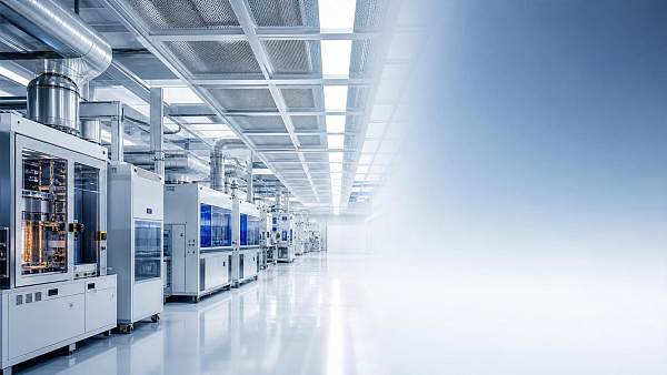
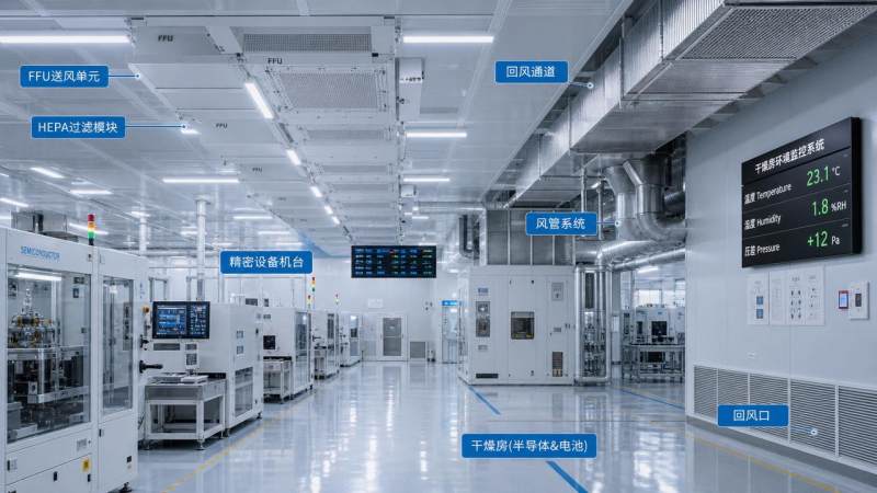
Semiconductor spaces rely on extremely stable laminar flow. During peak tool utilization, exhaust rates, process heat, and ceiling FFU loading can change faster than the system was tuned to handle.
Cleanroom thermal management fails here when supply air volume looks adequate on paper, but local turbulence forms around tools, chases, and return paths. Temperature may remain acceptable while contamination risk rises.
Key judgment points in wafer fab conditions
- FFU static pressure climbs as filters load unevenly.
- Process tools create localized thermal plumes.
- Subfab exhaust variation disrupts room balance.
- Control loops react to room averages, not micro-zones.
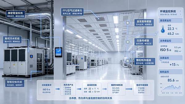
In this scenario, cleanroom thermal management should be checked through airflow visualization, pressure mapping, and micro-environment temperature tracking, not only by central chilled-water trends.
In battery dry rooms, latent load and dew point drift become the first warning signs
Battery coating and cell assembly spaces place extreme demands on moisture control. Peak loads often come from door openings, raw material movement, process exhaust swings, and partial regeneration inefficiency.
Here, cleanroom thermal management is tightly linked to desiccant wheel performance, regeneration temperature, air leakage, and envelope integrity. Sensible cooling alone cannot protect product quality.
Why dry rooms fail at high throughput
- Molecular sieve capacity drops when regeneration is unstable.
- Infiltration increases during frequent logistics movement.
- Bypass leakage around ducts or panels raises moisture load.
- Cooling coils may satisfy temperature while dew point worsens.
This makes cleanroom thermal management a psychrometric problem as much as a mechanical one. Any evaluation should include moisture balance under peak occupancy and transport activity.
In pharmaceutical and life science spaces, pressure stability can fail before thermal capacity
Pharmaceutical cleanrooms often require strict room pressure cascades. During batch changes, washdown, material transfer, or high personnel movement, pressure offsets can drift even when room temperature remains stable.
In these spaces, cleanroom thermal management must support containment and cleanliness together. A strong cooling system is not enough if door events or exhaust changes break directional airflow.
Core checks for regulated environments
- Pressure recovery time after door opening.
- Exhaust tracking accuracy during process changes.
- Humidity spikes from cleaning or sanitation events.
- Filter loading effects on air change rates.
These factors show why cleanroom thermal management should be validated against operational sequences, not only steady-state design points.
Typical peak-load differences across major applications
The hidden causes usually sit between systems, not inside one machine
Many peak-load investigations focus on chillers, CRAC units, or filter replacement alone. That approach misses the system interactions that define cleanroom thermal management under stress.
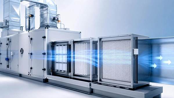
A loaded HEPA bank raises fan energy and reduces airflow. Lower airflow changes heat removal. That shifts room pressure. Then controls compensate slowly, creating oscillation instead of stability.
The same chain can start with exhaust imbalance, leaking dampers, poor sensor placement, or bad sequencing between make-up air and recirculation fans. Failures are often cumulative.
Frequent system-level blind spots
- Design based on average loads instead of simultaneous peaks.
- Static setpoints despite variable production states.
- No allowance for filter aging or coil fouling.
- Insufficient data at the tool or room sub-zone level.
How to match cleanroom thermal management strategy to the operating scene
Effective cleanroom thermal management starts with identifying the dominant peak-load driver. That driver may be heat, moisture, exhaust variation, occupancy, or contamination sensitivity.
Recommended adaptation actions
- Model peak states by production mode, not annual averages.
- Separate sensible and latent capacity review.
- Map airflow paths around equipment clusters and returns.
- Add sensor points at critical zones, not only central ducts.
- Test controls under step changes in exhaust and occupancy.
- Include filter loading and maintenance drift in capacity margins.
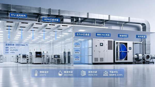
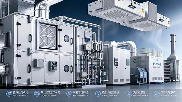
For facilities using precision CRAC units, FFUs, industrial scrubbers, workshop ventilation, and ERV systems together, integrated tuning is essential. Component efficiency means little without coordinated response.
This is where intelligence-led analysis becomes valuable. Cross-checking airflow, psychrometrics, filtration resistance, and energy recovery performance reveals why cleanroom thermal management succeeds or fails at scale.
Common misjudgments that distort peak-load decisions
One common mistake is assuming that stable room temperature means thermal control is healthy. In reality, cleanroom thermal management may already be failing through humidity drift, stagnant zones, or pressure instability.
Another mistake is oversizing cooling without checking airflow organization. More capacity cannot fix poor return design, overloaded FFUs, or delayed control sequences.
A third error is treating energy recovery or exhaust treatment as separate from room stability. In many facilities, ventilation interaction strongly shapes peak-load response.
Next steps for stronger cleanroom thermal management under real production pressure
Start with a peak-load audit built around actual operating scenes. Review process heat, moisture sources, filtration resistance, exhaust tracking, and control timing as one connected system.
Then compare room-level conditions with micro-environment behavior near tools, doors, returns, and transfer points. That gap often reveals the true weakness in cleanroom thermal management.
CECS follows this system view closely, connecting clean airflow, extreme humidity control, gas treatment, and energy recovery intelligence. It helps turn scattered data into practical decisions for resilient cleanroom thermal management.
When peak loads arrive, the winning facilities are not the coldest. They are the ones whose cleanroom thermal management remains balanced, measurable, and adaptive under the hardest conditions.
Recommended News
 Aug 18, 2026How to Evaluate a High-Tech HVAC Manufacturer for Cleanroom and Precision FacilitiesHigh-tech HVAC manufacturer evaluation guide for cleanrooms and precision facilities. Learn how to assess control stability, compliance, serviceability, and long-term operational risk.
 Aug 13, 2026How to Select VAV Airflow Control Systems for Labs and Cleanroom HVAC ProjectsVAV airflow control systems are critical for labs and cleanroom HVAC projects. Discover how to choose the right system for stability, compliance, and energy savings.
 Jul 21, 2026How to Evaluate Cleanroom Equipment Suppliers in the Middle East for New ProjectsCleanroom equipment Middle East supplier selection starts with technical fit, compliance, service, and lifecycle cost. Discover how to evaluate vendors and reduce project risk.
 Jul 19, 2026How to Estimate HVAC Cost for Electronics Manufacturing Cleanrooms and Production AreasElectronics manufacturing HVAC cost explained: learn how cleanroom class, humidity control, filtration, exhaust, and energy recovery shape realistic budgets and smarter project decisions.
 Jul 14, 2026Electronics Cleanroom Systems in Southeast Asia: How to Choose AHU, FFU, and HEPA LevelsElectronics cleanroom systems Southeast Asia: learn how to choose AHU, FFU, and HEPA levels for better yield, humidity control, energy efficiency, and long-term ROI.
 Jul 13, 2026Cleanroom Design Layout Basics: Zoning, Material Flow, and Contamination ControlCleanroom design layout basics explained: learn zoning, material and personnel flow, and contamination control strategies that reduce risk, improve compliance, and support efficient project planning.
 Jul 12, 2026Air Handling Units Supplier Checklist: 7 Specs to Compare Before You BuyAir handling units supplier checklist: compare 7 critical specs before you buy. Learn how to evaluate airflow, filtration, humidity control, efficiency, and compliance to cut risk and lifetime cost.
 Jul 11, 2026Cleanroom Equipment for Pharmaceutical Plants: What to Specify for GMP ComplianceCleanroom equipment for pharmaceutical plants: learn what to specify for GMP compliance, from airflow and HEPA filtration to pressure, humidity, and cleanability by process.
 Jul 11, 2026EU ETS Revision Reaches Cleanroom AHUsEU ETS revision brings Cleanroom AHUs into focus. Learn how the 2026 amendment affects CE DoC disclosure, carbon cost allocation, EPC tenders, and supplier selection before 2027.
 Jul 10, 2026Cleanroom AHU Cost Guide: Price Ranges, Configuration Factors, and Budget PlanningCleanroom AHU cost explained with realistic price ranges, key configuration factors, and budget tips to compare quotes, avoid hidden costs, and plan smarter cleanroom investments.
 Jul 09, 2026How to Select Precision Air Conditioning for Cleanrooms by Temperature, RH, and Particle RiskPrecision air conditioning for cleanrooms: learn how to choose the right system by temperature stability, RH control, and particle risk to protect yield, ensure compliance, and cut lifecycle cost.
![]() Jul 07, 2026How to Select Heat Recovery Ventilation Systems for Cleanrooms by Class and Air Change RateHeat recovery ventilation systems for cleanrooms: learn how to choose by ISO class, air change rate, leakage risk, and energy performance for safer, more efficient cleanroom operation.
Jul 07, 2026How to Select Heat Recovery Ventilation Systems for Cleanrooms by Class and Air Change RateHeat recovery ventilation systems for cleanrooms: learn how to choose by ISO class, air change rate, leakage risk, and energy performance for safer, more efficient cleanroom operation. Jul 06, 2026Semiconductor Clean Air Systems for Wafer Fabs: Key Design Factors for Yield ControlSemiconductor clean air systems for wafer fabs directly affect yield. Explore key design factors in airflow, AMC, humidity, and pressure control to improve fab stability.
 Jul 04, 2026When to Use Cleanroom Design Services: Scope, Deliverables, and Project Handover TipsCleanroom design services: learn when to engage specialists, what deliverables to request, and how smart handover planning reduces risk, protects compliance, and avoids costly rework.
 Jul 02, 2026How HVAC Humidity Stability Affects Yield in Semiconductor ManufacturingSemiconductor manufacturing HVAC humidity stability directly affects yield, ESD risk, contamination control, and uptime. Learn how stable humidity reduces defects and protects fab performance.
 Jul 02, 2026EN 1886:2026 Sets New EU Entry Bar for Cleanroom AHUsEN 1886:2026 raises the EU entry bar for cleanroom AHUs with new CE marking rules on micro-leakage and heat recovery. Learn what exporters, manufacturers, and buyers must do before 2027.
 Jul 01, 2026SEMI Semiconductor Cleanroom Solutions: What to Compare Before Planning a New FabSEMI semiconductor cleanroom solutions compared the right way: evaluate airflow, humidity, filtration, energy, and scalability before planning a new fab to protect yield and avoid costly redesign.
 Jun 30, 2026What a Clean Environment Control Systems Manufacturer Should Provide Beyond Basic HVACClean environment control systems manufacturer selection should go beyond HVAC. Learn how the right partner improves cleanliness, dew point control, compliance, and energy savings.
 Jun 29, 2026What Drives Cleanroom Temperature Control Cost in New Facility Projects?Cleanroom temperature control cost depends on ISO class, humidity precision, heat load, airflow, redundancy, and lifecycle energy use. Learn what truly drives budgets in new facility projects.
 Jun 27, 2026Electronics Cleanroom Systems Cost Breakdown: What Drives CapEx and Operating Expense?Electronics cleanroom systems cost more than equipment alone. Discover what drives CapEx and operating expense, from FFUs and humidity control to compliance, energy use, and lifecycle risk.
 Jun 25, 2026Clean Environment Control Systems vs Traditional HVAC: Which Fits Sensitive Production?Clean environment control systems vs traditional HVAC: discover which solution better protects sensitive production, improves compliance, and reduces costly contamination risk.
 Jun 25, 2026Electronics Cleanroom Solutions: How to Choose FFU, AHU, and HEPA SetupsElectronics cleanroom solutions explained: learn how to choose FFU, AHU, and HEPA setups to improve yield, control airflow, and reduce lifecycle costs.
 Jun 24, 2026Cleanroom Airflow Control vs Pressure Control: What Matters More for Contamination Risk?Cleanroom airflow control vs pressure control: discover which factor has the bigger impact on contamination risk, product protection, compliance, and cleanroom performance.
 Jun 23, 2026How to Set Cleanroom Temperature Regulation for Stable Processes and Product QualityCleanroom temperature regulation starts with process needs, not generic setpoints. Learn how to control temperature, humidity, airflow, and deviations for stable quality and higher yield.