Search News
Industry Portal
Hot Articles
- How Factories Can Select Air Quality Controls for Dust, Fumes, and VOCsIndustrial air quality control for factories: learn how to select effective solutions for dust, fumes, and VOCs while improving safety, compliance, energy efficiency, and uptime.
- How to Size Industrial Gas Scrubbing Units for Acid Fumes and Variable AirflowsIndustrial gas scrubbing units: learn how to size acid-fume scrubbers for variable airflows, peak loads, chemical demand, pressure drop, and reliable compliance.
- How to Evaluate Industrial Air Quality Control Systems for Dust, Fumes, and VOCsIndustrial air quality control systems: learn how to evaluate dust, fumes, and VOC solutions by capture efficiency, compliance, maintenance, and lifecycle cost.
Popular Tags
Why cleanroom thermal efficiency affects process stability
author
Time
Click Count

For technical evaluators, cleanroom thermal efficiency is not just an energy KPI. It is a direct indicator of how reliably a controlled space can maintain airflow pattern, temperature uniformity, humidity stability, and particle behavior under real production load.
In practice, poor thermal performance often appears first as process drift rather than obvious HVAC failure. A room may still meet average setpoints, yet local heat accumulation, unstable return conditions, or uneven sensible loads can quietly undermine yield.
That is why the question behind cleanroom thermal efficiency is usually not “How much energy can we save?” but “Will this system hold the process window when equipment heat, occupancy, and outdoor conditions change?”
Why cleanroom thermal efficiency matters more than its utility bill impact
Technical evaluators typically search this topic to understand the link between thermal design and process stability. They need to know whether thermal efficiency improves control robustness or creates hidden risks through undersized airflow, slow response, or uneven cooling.
The most useful answer is straightforward: thermal efficiency affects process stability because it determines how precisely the cleanroom removes heat, maintains laminar or directional airflow, controls moisture, and limits thermal gradients around sensitive tools and materials.
When thermal efficiency is weak, control systems work harder but achieve less. Fans, coils, desiccant stages, filtration modules, and recirculation paths may still operate, yet the room experiences wider fluctuations between supply conditions and actual point-of-use conditions.
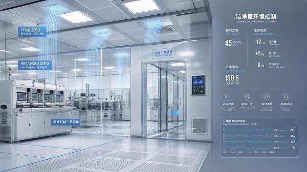
For semiconductor fabs, battery coating lines, optics assembly, pharmaceutical filling, and precision electronics, those fluctuations can become process defects. Temperature excursions alter material behavior, humidity drift changes electrostatic conditions, and local turbulence increases contamination transport.
So the evaluation priority should not be energy efficiency in isolation. It should be thermal efficiency as a stability function: how effectively the cleanroom converts cooling, dehumidification, and airflow power into repeatable environmental conditions at the process location.
What technical evaluators usually need to verify first
Target readers in technical assessment roles are rarely satisfied with generic HVAC explanations. They want evidence that a cleanroom system can maintain thermal control under dynamic loads, startup transitions, maintenance events, and seasonal extremes.
In most evaluations, the central concerns are fivefold: temperature uniformity, humidity precision, airflow consistency, control response speed, and resilience under partial failure or changing process loads. These factors directly affect acceptance risk and lifecycle performance.
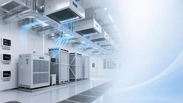
They also need to distinguish between nameplate efficiency and operational efficiency. A CRAC unit, FFU field, or energy recovery stage may look efficient on paper, while actual room performance suffers from bypass air, poor zoning, control lag, or bad sensor placement.
Therefore, the strongest article structure is not theoretical thermodynamics alone. It should help evaluators connect thermal performance with measurable room behavior, process sensitivity, equipment selection criteria, and commissioning checkpoints.
How thermal efficiency influences airflow stability and contamination control
Many process problems start with airflow instability, and airflow instability often starts with thermal imbalance. In a cleanroom, heat sources from tools, motors, lighting, people, and envelope gain create buoyancy effects that can distort intended airflow patterns.
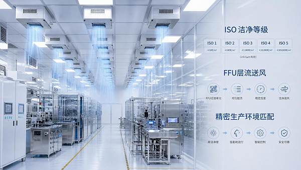
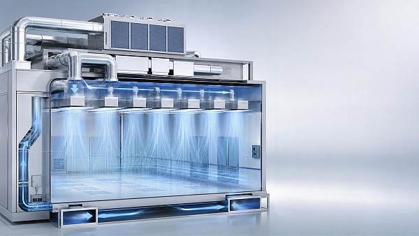
If the thermal control system removes sensible heat unevenly, warmer plumes rise and interfere with vertical laminar flow or unidirectional air distribution. This increases mixing, creates recirculation pockets, and raises the chance that particles move into critical process zones.
Even where HEPA or ULPA filtration is excellent, poor thermal efficiency can reduce effective cleanliness. The issue is not just filter capture efficiency; it is whether the air reaches and leaves the process area in a stable, predictable manner.
In wafer fabs, for example, local thermal lift near process tools can alter downflow uniformity over open handling areas. In battery coating environments, unstable heat removal can influence solvent behavior and drying consistency while changing airborne contaminant trajectories.
Technical evaluators should therefore review not only airflow volume but also the thermal logic behind the airflow system. Ask whether fan energy, supply temperature, return configuration, and ceiling-to-floor pressure relationships work together to preserve designed flow fields.
Why temperature uniformity matters more than average room temperature
A cleanroom can meet a nominal 22°C setpoint and still be thermally unstable. Average room temperature does not reveal whether one aisle is 21.2°C, another is 23.0°C, and a tool inlet is cycling around a much wider band.
Process stability depends far more on spatial uniformity and temporal consistency than on a single average value. Sensitive manufacturing steps respond to local conditions at the tool, substrate, web, chemical bath, or operator interface point.
This is where cleanroom thermal efficiency becomes practical. An efficient thermal system delivers the required condition with minimal overshoot, minimal dead zone, and minimal variation between supply intent and process-area reality.
Poor efficiency often shows up as excessive reheat, simultaneous cooling and reheating, uneven coil loading, or weak zoning logic. These conditions waste energy, but more importantly, they create unstable control loops that broaden environmental fluctuation.
For evaluators, a key question is not merely “What is the setpoint?” It is “What is the maximum point-to-point and time-based deviation during normal production, peak tool load, door events, and utility transitions?”
The hidden link between thermal efficiency and humidity precision
Humidity control in cleanrooms is tightly coupled to thermal behavior. When sensible heat removal, airflow rate, and dehumidification capacity are not balanced correctly, the room may experience moisture instability even if the humidity system itself appears adequately sized.
This is especially critical in semiconductor, lithium battery, and precision coating applications. In these environments, humidity excursions can trigger hydrolysis risk, affect material adhesion, change solvent evaporation rates, and increase electrostatic discharge probability.
Thermal inefficiency can worsen humidity control in several ways. It may force coils into unstable operating ranges, reduce dew-point consistency, increase infiltration through pressure fluctuations, or require aggressive reheating that complicates moisture balance.
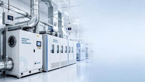
In ultra-low dew point spaces, such as dry rooms paired with desiccant wheels and precision CRAC units, thermal recovery and sensible load management must be carefully coordinated. Otherwise, latent control becomes vulnerable to heat spikes and return-air variation.
Technical evaluators should examine whether the system maintains both dry-bulb and dew point stability under changing process heat. A room that holds temperature but drifts in moisture is not thermally efficient in any meaningful process sense.
How process equipment heat loads expose weak thermal design
Cleanroom thermal performance is often judged under standard conditions, but real process stability is tested by equipment behavior. Tool heat rejection is rarely static. It changes with batch timing, idle states, maintenance access, and production intensity.
If thermal efficiency is marginal, these changing loads create microclimate swings around process tools. Return air may capture heat too slowly, supply air may short-circuit before reaching the hot zone, or local recirculation may trap heat near sensitive surfaces.
This is why evaluators should request load maps instead of relying only on total room tonnage. The location, density, intermittency, and vertical profile of sensible loads matter as much as the aggregated cooling capacity.
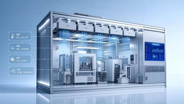
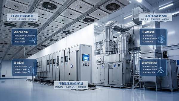
A high-performing design considers where heat is generated, how it rises or spreads, and how the airflow path removes it without compromising cleanliness. This may involve localized extraction, tighter zoning, optimized FFU arrays, or revised return-air geometry.
In short, thermal efficiency supports process stability only when it matches the real thermal topology of the cleanroom, not just the theoretical room volume and nominal occupancy assumptions from early design stages.
What to look for in system design and equipment selection
For technical evaluators comparing solutions, the most important design question is whether the system architecture supports stable environmental delivery at the process level. Efficiency claims should be tested against control precision, redundancy strategy, and field adaptability.
Start with air-side design. Check supply temperature control range, fan turndown capability, FFU uniformity, pressure cascade logic, return-air placement, and whether airflow remains stable during filter loading, maintenance states, and production mode changes.
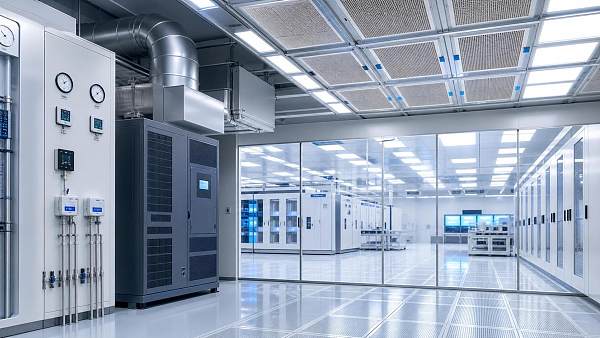
Then review cooling and dehumidification components. Precision CRAC units, chilled water coils, desiccant wheels, and reheat stages should be assessed for part-load behavior, control resolution, response time, and integration with room-level sensors.
Control architecture is equally important. Distributed sensing, accurate sensor placement, and coordinated control between room units and central systems determine whether thermal efficiency is translated into stable operation or lost through lag and hunting.
Finally, assess recoverability. After a door opening, tool startup, or upstream utility disturbance, how quickly can the system return the room to specification without overshoot? Recovery performance is one of the clearest indicators of useful thermal efficiency.
Commissioning metrics that reveal whether thermal efficiency is real
Many cleanrooms are accepted based on broad compliance checks, yet process instability appears later because commissioning focused on average values rather than operational robustness. Evaluators should push for performance verification under realistic load scenarios.
Useful metrics include point-to-point temperature deviation, temporal stability at critical points, dew point variance, airflow visualization under full tool load, recovery time after disturbance, and energy use normalized against control precision achieved.
Trend data is more valuable than snapshots. A system may pass a single test window and still exhibit cyclical instability over shifts, tool recipes, or outside-air changes. Continuous trending can reveal control oscillation, local hot spots, and recurring humidity drift.
It is also wise to compare design intent with actual measured airflow and thermal distribution. Computational fluid dynamics can support design decisions, but field verification remains essential because installation details often change real behavior.
For buyers and evaluators, the lesson is simple: thermal efficiency should be proven as stable environmental output under disturbance, not assumed from equipment efficiency ratings or theoretical load calculations alone.
Common evaluation mistakes that lead to unstable cleanroom performance
One frequent mistake is focusing too heavily on nominal energy savings while underweighting control resolution. A lower-energy design that cannot maintain process conditions is not efficient in any operational or financial sense.
Another mistake is evaluating components independently. FFUs, CRAC units, scrubbers, ventilation paths, and recovery devices interact thermally. A strong component can still underperform within a weak system arrangement or poorly tuned controls framework.
Sensor strategy is also often underestimated. If temperature and humidity sensors are placed in low-risk areas instead of near critical process zones, the control system may maintain misleading averages while process-adjacent conditions drift out of tolerance.
Some teams also ignore lifecycle degradation. Filter loading, coil fouling, fan wear, and damper drift can gradually reduce thermal efficiency. Evaluation should include serviceability, monitoring capability, and how performance is maintained over time.
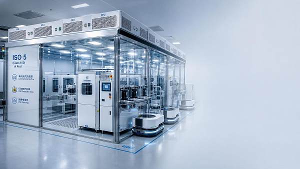
Lastly, do not assume process stability from cleanliness class alone. ISO compliance on particles does not automatically mean thermal adequacy. Many yield issues emerge from subtle thermal and moisture instability rather than obvious particulate failure.
How to make a better technical decision
When evaluating a cleanroom solution, frame the decision around process protection first, then energy optimization second. The best system is the one that delivers stable thermal conditions to the process with the lowest total risk and sustainable lifecycle cost.
Ask vendors to show how their design handles real disturbances, nonuniform tool loads, low-dew-point demands, and airflow preservation. Request data, not only claims: mapped temperatures, recovery curves, trend logs, and control strategy descriptions.
Look for evidence that thermal efficiency improves operational consistency. That includes reduced hot spots, narrower dew point variation, stable pressure hierarchy, predictable airflow paths, and less control hunting during part-load operation.
Also consider expandability. High-tech manufacturing environments evolve. A thermally efficient cleanroom should tolerate future tool additions, revised process density, and stricter environmental limits without requiring complete system replacement.
For technical evaluators, this approach creates a more accurate procurement and design framework. It aligns environmental control decisions with actual manufacturing outcomes rather than isolated utility metrics or simplified equipment comparisons.
Conclusion
Cleanroom thermal efficiency affects process stability because it governs how consistently the room removes heat, controls moisture, preserves airflow intent, and responds to changing loads. In sensitive production environments, these functions directly influence contamination risk and yield.
For technical evaluators, the right question is not whether a system is efficient in theory, but whether it converts that efficiency into stable, measurable environmental control at the point where the process is most vulnerable.
That is the standard worth applying to CRAC units, FFU fields, dry-room systems, ventilation layouts, and control architectures alike. When thermal efficiency is evaluated through the lens of process stability, better technical and commercial decisions follow.
Recommended News
 Aug 25, 2026How to Select Cleanroom Particle Control Equipment for ISO Class and Process RiskCleanroom particle control equipment selection starts with process risk, ISO class, and airflow design. Learn how to compare FFUs, filters, and monitoring for reliable performance.
 Aug 23, 2026How Laminar Airflow Supports Compliance and Contamination Control in Medical Device ManufacturingLaminar airflow for medical devices helps reduce contamination risk, support cleanroom compliance, and improve audit readiness—see how it protects product quality and manufacturing control.
 Aug 21, 2026How to Achieve Stable RH Precision Humidity Control in Cleanroom Production?Stable RH precision humidity control starts with process-based design. Learn how airflow, sensors, dehumidification, and recovery logic keep cleanroom production consistent and reliable.
 Aug 19, 2026What Drives Cleanroom Compliance Cost in Pharma and Semiconductor Projects?Cleanroom compliance cost in pharma and semiconductor projects depends on ISO class, airflow, humidity control, validation, and energy use. Learn what drives cost and how to avoid costly overdesign.
 Aug 11, 2026How to Select Precision Humidity Control for Cleanrooms and Micro-EnvironmentsPrecision humidity control for cleanrooms starts with process needs. Learn how to compare dew point targets, airflow, controls, and energy tradeoffs for reliable, high-yield micro-environments.
 Aug 05, 2026How Cleanroom Environmental Control Automation Improves Compliance and StabilityCleanroom environmental control automation improves compliance, stability, and audit readiness through faster response, traceable control logic, and consistent environmental performance.
 Aug 04, 2026How Smart Cleanroom Thermal Control Improves Stability in FFU-Based Micro-EnvironmentsSmart cleanroom thermal control improves FFU-based micro-environment stability by aligning temperature, humidity, pressure, and airflow—learn what to evaluate before performance drifts.
 Aug 03, 2026Semiconductor Cleanroom Standards Explained: ISO Classes, Air Changes, and ESD ControlsCleanroom standards for semiconductor industry explained: understand ISO classes, air changes, and ESD controls to improve yield, reduce contamination risk, and choose smarter fab environments.
 Jul 30, 2026How to Choose Environmental Control Solutions for High-Tech Manufacturing FacilitiesHigh-tech manufacturing environment solutions guide: learn how to evaluate cleanroom airflow, dew point control, exhaust treatment, and compliance to protect yield and cut lifecycle risk.
 Jul 29, 2026How to Design Ventilation for Precision Manufacturing to Control Particles and HeatPrecision manufacturing ventilation design guide: learn how to control particles, heat, airflow, filtration, and pressure for cleaner production, higher yield, and more reliable operations.
 Jul 26, 2026ISO 5 Semiconductor Cleanroom Solutions: Key Design Criteria for Process StabilityISO 5 semiconductor cleanroom solutions focus on process stability, airflow uniformity, pressure control, and thermal consistency to protect yield and improve fab performance.
 Jul 24, 2026Cleanroom Standards Compliance: Key Requirements and Audit Readiness ChecklistCleanroom standards compliance starts with real control, not paperwork. Explore key ISO requirements, common audit gaps, and a practical checklist to improve readiness.
 Jul 20, 2026How to Evaluate a Semiconductor Cleanroom Solutions Supplier for Fab ProjectsSemiconductor cleanroom solutions supplier selection can make or break fab performance. Learn how to compare engineering depth, compliance, delivery, and lifecycle value.
 Jul 15, 2026Dust-Free Manufacturing: Key Process Controls for Cleaner Production LinesDust-free manufacturing starts with tighter control of airflow, humidity, filtration, and gas capture. Discover how cleaner production lines improve yield, safety, compliance, and energy performance.
 Jul 13, 2026How Semiconductor Environmental Control AMC Reduction Prevents Yield LossSemiconductor environmental control AMC reduction is essential to prevent yield loss. Learn how airflow, humidity, filtration, and gas treatment protect fabs and improve process stability.
 Jul 12, 2026How to Choose Semiconductor Cleanroom Solutions for EUV Lithography LinesSemiconductor cleanroom solutions for EUV require more than ISO class compliance. Learn how to compare airflow, AMC, thermal stability, vibration, and lifecycle cost for better yield.
 Jul 11, 2026Cleanroom Design Criteria Explained: Air Changes, Pressure Cascade, and ISO ClassCleanroom design criteria explained: learn how air changes, pressure cascade, and ISO Class work together to improve contamination control, compliance, and process stability.
 Jul 09, 2026Semiconductor Facility Ventilation Standards: Pressure Cascade, Air Changes, and ComplianceSemiconductor facility ventilation explained: pressure cascade, air changes, and compliance essentials to protect yield, control contamination, and reduce hidden operational risk.
 Jul 09, 2026Clean Environment Control Solutions for Dust, Humidity, and ESD in Sensitive ProductionClean environment control solutions for dust, humidity, and ESD help sensitive production improve yield, ensure compliance, cut energy waste, and reduce costly rework.
 Jul 08, 2026Cleanroom Standards ISO Class Explained: How to Match Class Levels to ProductionCleanroom standards ISO class explained clearly: learn how to match class levels to production needs, reduce contamination risk, control costs, and choose smarter cleanroom strategies.
 Jul 08, 2026How Electronics Cleanroom Air Showers Reduce Particle Transfer at Entry PointsElectronics cleanroom air showers reduce particle transfer at entry points, protect sensitive processes, and support better yield, cleaner airflow, and more reliable contamination control.
![]() Jul 07, 2026Cleanroom Certification USA: ISO Classes, Testing Steps, and Common Compliance GapsCleanroom certification USA explained: compare ISO classes, understand key testing steps, and spot common compliance gaps before they trigger audit issues, downtime, or product risk.
Jul 07, 2026Cleanroom Certification USA: ISO Classes, Testing Steps, and Common Compliance GapsCleanroom certification USA explained: compare ISO classes, understand key testing steps, and spot common compliance gaps before they trigger audit issues, downtime, or product risk. Jul 06, 2026What Is Semiconductor Clean Air and Why Does It Matter in Contamination Control?Semiconductor clean air is vital to contamination control, protecting yield, tool stability, and process consistency. Learn why it matters in modern fabs.
 Jul 05, 2026Cleanroom Airflow Control Systems Explained: How to Balance Pressure, Air Changes, and StabilityCleanroom airflow control systems explained: learn how to balance pressure, air changes, and stability to improve contamination control, cut energy waste, and protect production yield.