Search News
Industry Portal
Hot Articles
- ISO 14644 Certification Process: From Cleanroom Testing to Compliance ApprovalISO 14644 certification process explained: prepare your cleanroom, complete particle testing, address failures, and achieve compliance approval with confidence.
- How Factories Can Select Air Quality Controls for Dust, Fumes, and VOCsIndustrial air quality control for factories: learn how to select effective solutions for dust, fumes, and VOCs while improving safety, compliance, energy efficiency, and uptime.
- How to Size Industrial Gas Scrubbing Units for Acid Fumes and Variable AirflowsIndustrial gas scrubbing units: learn how to size acid-fume scrubbers for variable airflows, peak loads, chemical demand, pressure drop, and reliable compliance.
Popular Tags
Why cleanroom thermal management fails under peak loads
author
Time
Click Count

Cleanroom thermal management often appears stable during normal operation, yet peak loads expose hidden weaknesses in airflow balance, cooling capacity, humidity control, and control logic.
The real concern is not average setpoint compliance. It is whether process stability survives tool ramp-up, filter loading, outdoor swings, and changing occupancy.
In high-tech manufacturing, this edge condition defines yield, safety, energy use, and audit confidence. Cleanroom thermal management must therefore be judged under stress.
Cleanroom Thermal Management as a Stability Discipline
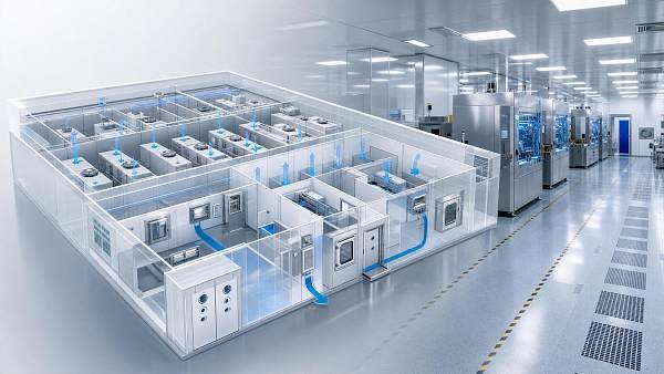
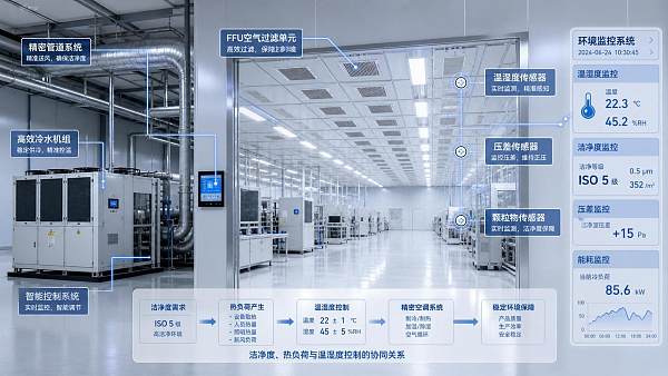
Cleanroom thermal management is the coordinated control of temperature, humidity, airflow, pressure, filtration, and heat removal inside controlled environments.
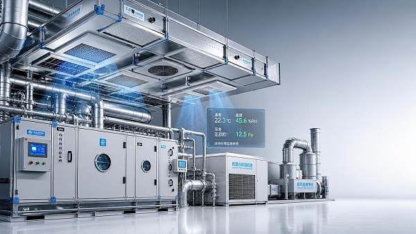
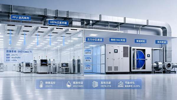
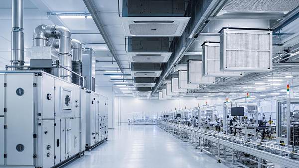
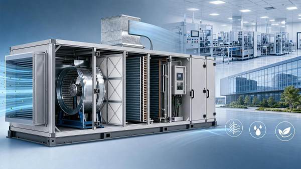
It connects CRAC units, fan filter units, chilled water systems, sensors, exhaust paths, dampers, and automation logic into one operating ecosystem.
The system must do more than cool air. It must protect process windows, particle control, personnel comfort, and regulatory expectations simultaneously.
Peak-load failure occurs when one part reaches its limit before the whole system appears overloaded. This is why failures often surprise operators.
A fab may have enough installed cooling capacity, yet still lose control because airflow distribution, coil response, or humidity removal becomes constrained.
Effective cleanroom thermal management therefore depends on capacity, distribution, sequencing, measurement accuracy, and dynamic response under abnormal but predictable events.
Industry Conditions That Intensify Peak Loads
Modern cleanrooms face denser tools, tighter process tolerances, lower dew points, higher exhaust rates, and stronger energy-performance expectations.
These factors compress the safety margin available to cleanroom thermal management, especially in semiconductor, battery, optics, pharmaceutical, and precision assembly sites.
The current focus is not simply larger equipment. It is resilient cleanroom thermal management with transparent margins and faster fault recognition.
As cleanrooms pursue decarbonization, recovery ventilation, variable airflow, and digital control, interactions become more complex during peak demand.
Why Peak Loads Reveal Hidden Weaknesses
Cooling capacity is available but not deliverable
Many facilities calculate installed capacity correctly, yet fail to verify whether cooling reaches the exact heat source at the right moment.
A CRAC unit may have spare tonnage, while ceiling airflow, return paths, or coil valve authority restrict effective heat removal.
This makes cleanroom thermal management vulnerable to local overload, even when plant-level dashboards show acceptable reserves.
Airflow balance shifts under filter loading
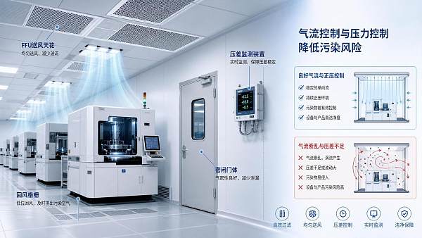
Fan filter units support laminar flow, particle control, and temperature distribution. Their performance changes as filters load.
If static pressure margins are weak, cleanroom thermal management loses vertical uniformity before alarms indicate a dramatic failure.
The result can be temperature stratification, turbulent mixing, and process-side drift near sensitive tools or work zones.
Humidity control becomes the limiting factor
In battery coating, lithography, and precision materials handling, humidity may be more decisive than dry-bulb temperature.
Peak moisture loads can come from makeup air, door openings, personnel, wet processes, or regeneration instability in desiccant wheels.
When latent capacity is insufficient, cleanroom thermal management may hold temperature while dew point quietly exceeds the process limit.
Control logic reacts too slowly
Automation may be tuned for steady operation, not sudden load changes. Slow sensors and conservative PID loops create lag.
Equipment sequencing can also conflict. Chillers, valves, reheaters, humidifiers, and exhaust controls may fight each other.
In peak-load periods, cleanroom thermal management depends on coordinated logic rather than isolated equipment performance.
Business Value of Robust Cleanroom Thermal Management
The value of cleanroom thermal management is measured through avoided losses, stable output, predictable audits, and controlled energy consumption.
Temperature or humidity excursions can reduce yield long before a full production stop occurs. The cost is often hidden in scrap rates.
Reliable environmental control also supports compliance with ISO 14644 principles, internal quality rules, and customer qualification requirements.
- It protects nanoscale process repeatability in semiconductor and optics facilities.
- It reduces moisture-related defects in lithium battery and advanced materials production.
- It stabilizes operator comfort without compromising air cleanliness or pressure cascades.
- It enables energy optimization without cutting essential resilience margins.
A balanced strategy does not oversize everything. It defines where redundancy matters and where intelligent modulation can reduce waste.
This is central to cleanroom thermal management in facilities that must combine absolute cleanliness with ultimate energy saving.
Typical Failure Objects and Scenarios
Peak-load failures usually concentrate around recurring objects. These patterns help teams inspect risk before visible deviation occurs.
This classification turns cleanroom thermal management from a broad concept into a practical diagnostic roadmap.
It also supports better root-cause separation between mechanical limits, airflow problems, sensor errors, and automation logic.
Practical Assessment Methods Before Failure
A credible assessment must recreate the operating edge. Nameplate reviews alone cannot confirm cleanroom thermal management resilience.
- Trend temperature, dew point, pressure, airflow, and valve position during planned production peaks.
- Measure local conditions near heat-generating tools, not only at room reference sensors.
- Check filter pressure drop against fan capability and airflow uniformity requirements.
- Review chilled water temperature, coil performance, and control valve authority.
- Test desiccant regeneration stability during high outdoor humidity periods.
- Validate alarm thresholds against process limits, not only comfort standards.
Data resolution matters. Five-minute averages can hide short excursions that damage sensitive processes.
For stronger cleanroom thermal management, high-frequency logging should capture transitions, tool starts, door events, and exhaust changes.
Computational fluid dynamics can support design verification, but field measurement remains essential after installation and process changes.
Design and Operation Practices That Improve Resilience
Resilient cleanroom thermal management begins with realistic load profiles. Static peak assumptions should be replaced with dynamic operating scenarios.
Tool ramp curves, maintenance modes, cleaning cycles, personnel peaks, and seasonal outdoor conditions must be included in validation.
- Preserve airflow margin: select FFUs and fans with allowance for filter loading.
- Separate sensible and latent risks: evaluate temperature and dew point independently.
- Improve return-air capture: avoid heat recirculation near dense tool zones.
- Coordinate controls: tune sequences across chillers, coils, reheaters, and exhaust systems.
- Use predictive maintenance: link filter, valve, sensor, and fan trends to early warnings.
Energy recovery ventilation, variable airflow, and heat recovery can reduce operating costs. They must not create unstable pressure or humidity behavior.
The best cleanroom thermal management strategy treats efficiency and resilience as paired targets, not competing priorities.
Governance, Compliance, and Lifecycle Attention
Cleanroom conditions drift over time. New tools, filter replacement delays, recalibrated sensors, and changed recipes alter the original balance.
Lifecycle governance should include periodic requalification, seasonal stress tests, and change-impact reviews for all process modifications.
Documentation is equally important. Trend reports, calibration records, airflow maps, and response tests support compliance conversations.
For ISO 14644 aligned environments, cleanroom thermal management supports contamination control indirectly through airflow stability and pressure discipline.
A facility may pass particle counts during calm conditions, yet struggle when peak heat loads disturb laminar flow patterns.
This is why environmental control evidence should reflect real operating states, not only ideal commissioning conditions.
Action Path for More Reliable Performance
Start by identifying the three most severe peak-load scenarios in the facility. Then collect synchronized environmental and equipment data.
Compare process limits with actual short-duration deviations. Separate comfort alarms from quality-critical thresholds.
Next, rank constraints by impact: airflow delivery, cooling coil capacity, humidity removal, control delay, or sensor placement.
A targeted improvement plan should include quick operational fixes, medium-term control tuning, and long-term equipment or layout upgrades.
CECS intelligence focuses on these hidden environmental limits across CRAC units, FFU arrays, desiccant systems, scrubbers, ventilation, and ERV platforms.
For any controlled environment, cleanroom thermal management should be evaluated where failure actually begins: at the edge of peak demand.
The next practical step is a peak-load readiness review, supported by trend data, field measurements, and process-specific acceptance criteria.
That review turns cleanroom thermal management from a reactive maintenance topic into a measurable foundation for yield, compliance, and energy discipline.
Recommended News
 Aug 18, 2026How to Evaluate a High-Tech HVAC Manufacturer for Cleanroom and Precision FacilitiesHigh-tech HVAC manufacturer evaluation guide for cleanrooms and precision facilities. Learn how to assess control stability, compliance, serviceability, and long-term operational risk.
 Aug 13, 2026How to Select VAV Airflow Control Systems for Labs and Cleanroom HVAC ProjectsVAV airflow control systems are critical for labs and cleanroom HVAC projects. Discover how to choose the right system for stability, compliance, and energy savings.
 Jul 21, 2026How to Evaluate Cleanroom Equipment Suppliers in the Middle East for New ProjectsCleanroom equipment Middle East supplier selection starts with technical fit, compliance, service, and lifecycle cost. Discover how to evaluate vendors and reduce project risk.
 Jul 19, 2026How to Estimate HVAC Cost for Electronics Manufacturing Cleanrooms and Production AreasElectronics manufacturing HVAC cost explained: learn how cleanroom class, humidity control, filtration, exhaust, and energy recovery shape realistic budgets and smarter project decisions.
 Jul 14, 2026Electronics Cleanroom Systems in Southeast Asia: How to Choose AHU, FFU, and HEPA LevelsElectronics cleanroom systems Southeast Asia: learn how to choose AHU, FFU, and HEPA levels for better yield, humidity control, energy efficiency, and long-term ROI.
 Jul 13, 2026Cleanroom Design Layout Basics: Zoning, Material Flow, and Contamination ControlCleanroom design layout basics explained: learn zoning, material and personnel flow, and contamination control strategies that reduce risk, improve compliance, and support efficient project planning.
 Jul 12, 2026Air Handling Units Supplier Checklist: 7 Specs to Compare Before You BuyAir handling units supplier checklist: compare 7 critical specs before you buy. Learn how to evaluate airflow, filtration, humidity control, efficiency, and compliance to cut risk and lifetime cost.
 Jul 11, 2026Cleanroom Equipment for Pharmaceutical Plants: What to Specify for GMP ComplianceCleanroom equipment for pharmaceutical plants: learn what to specify for GMP compliance, from airflow and HEPA filtration to pressure, humidity, and cleanability by process.
 Jul 11, 2026EU ETS Revision Reaches Cleanroom AHUsEU ETS revision brings Cleanroom AHUs into focus. Learn how the 2026 amendment affects CE DoC disclosure, carbon cost allocation, EPC tenders, and supplier selection before 2027.
 Jul 10, 2026Cleanroom AHU Cost Guide: Price Ranges, Configuration Factors, and Budget PlanningCleanroom AHU cost explained with realistic price ranges, key configuration factors, and budget tips to compare quotes, avoid hidden costs, and plan smarter cleanroom investments.
 Jul 09, 2026How to Select Precision Air Conditioning for Cleanrooms by Temperature, RH, and Particle RiskPrecision air conditioning for cleanrooms: learn how to choose the right system by temperature stability, RH control, and particle risk to protect yield, ensure compliance, and cut lifecycle cost.
![]() Jul 07, 2026How to Select Heat Recovery Ventilation Systems for Cleanrooms by Class and Air Change RateHeat recovery ventilation systems for cleanrooms: learn how to choose by ISO class, air change rate, leakage risk, and energy performance for safer, more efficient cleanroom operation.
Jul 07, 2026How to Select Heat Recovery Ventilation Systems for Cleanrooms by Class and Air Change RateHeat recovery ventilation systems for cleanrooms: learn how to choose by ISO class, air change rate, leakage risk, and energy performance for safer, more efficient cleanroom operation. Jul 06, 2026Semiconductor Clean Air Systems for Wafer Fabs: Key Design Factors for Yield ControlSemiconductor clean air systems for wafer fabs directly affect yield. Explore key design factors in airflow, AMC, humidity, and pressure control to improve fab stability.
 Jul 04, 2026When to Use Cleanroom Design Services: Scope, Deliverables, and Project Handover TipsCleanroom design services: learn when to engage specialists, what deliverables to request, and how smart handover planning reduces risk, protects compliance, and avoids costly rework.
 Jul 02, 2026How HVAC Humidity Stability Affects Yield in Semiconductor ManufacturingSemiconductor manufacturing HVAC humidity stability directly affects yield, ESD risk, contamination control, and uptime. Learn how stable humidity reduces defects and protects fab performance.
 Jul 02, 2026EN 1886:2026 Sets New EU Entry Bar for Cleanroom AHUsEN 1886:2026 raises the EU entry bar for cleanroom AHUs with new CE marking rules on micro-leakage and heat recovery. Learn what exporters, manufacturers, and buyers must do before 2027.
 Jul 01, 2026SEMI Semiconductor Cleanroom Solutions: What to Compare Before Planning a New FabSEMI semiconductor cleanroom solutions compared the right way: evaluate airflow, humidity, filtration, energy, and scalability before planning a new fab to protect yield and avoid costly redesign.
 Jun 30, 2026What a Clean Environment Control Systems Manufacturer Should Provide Beyond Basic HVACClean environment control systems manufacturer selection should go beyond HVAC. Learn how the right partner improves cleanliness, dew point control, compliance, and energy savings.
 Jun 29, 2026What Drives Cleanroom Temperature Control Cost in New Facility Projects?Cleanroom temperature control cost depends on ISO class, humidity precision, heat load, airflow, redundancy, and lifecycle energy use. Learn what truly drives budgets in new facility projects.
 Jun 27, 2026Electronics Cleanroom Systems Cost Breakdown: What Drives CapEx and Operating Expense?Electronics cleanroom systems cost more than equipment alone. Discover what drives CapEx and operating expense, from FFUs and humidity control to compliance, energy use, and lifecycle risk.
 Jun 25, 2026Clean Environment Control Systems vs Traditional HVAC: Which Fits Sensitive Production?Clean environment control systems vs traditional HVAC: discover which solution better protects sensitive production, improves compliance, and reduces costly contamination risk.
 Jun 25, 2026Electronics Cleanroom Solutions: How to Choose FFU, AHU, and HEPA SetupsElectronics cleanroom solutions explained: learn how to choose FFU, AHU, and HEPA setups to improve yield, control airflow, and reduce lifecycle costs.
 Jun 24, 2026Cleanroom Airflow Control vs Pressure Control: What Matters More for Contamination Risk?Cleanroom airflow control vs pressure control: discover which factor has the bigger impact on contamination risk, product protection, compliance, and cleanroom performance.
 Jun 23, 2026How to Set Cleanroom Temperature Regulation for Stable Processes and Product QualityCleanroom temperature regulation starts with process needs, not generic setpoints. Learn how to control temperature, humidity, airflow, and deviations for stable quality and higher yield.